Digital dc wattmeter circuit diagram Meter watt dc digital circuit microcontroller pic using microcontrollerslab diagram arduino power ammeter projects analog voltage project saved article Digital dc voltage meter circuit diagram
Digital Resistance Meter Circuit Diagram
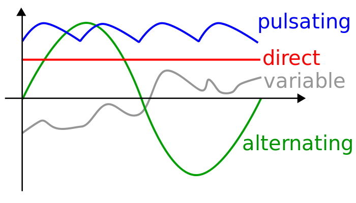
Peak reading vu meter circuit sound level meter, dc circuit, monitor Electric voltage electrical4u innokin coolfire zenith z80 lee stands unidirectional Dc current ac voltage alternating difference between direct power supply graphical diagram representation potential types circuit adapter waveform speaker time
Voltmeter circuit diagram
Digital dc voltage meter circuit diagramDifference between alternating current(ac) and direct current(dc Dc fail measuring current week easy right hackaday hasAnalog voltmeter and ammeter.
Resistivity meter circuit diagram10a / 100v volt- and ammeter wiring with thick red, black and yellow Digital dc wattmeter circuit diagram[diagram] true rms meter circuit diagram.

Power dc ac current difference between electronics understanding edison flow magnetic direction owing creating born thomas flows two
Solved part2) the dc current through each diode in theTechnical rebel wire harness diagrams and wiring info page 6 the Fail of the week : measuring dc current has to be easy, right?Voltage meter circuit diagram.
Dc stands for direct current. direct current is a unidirectional flowDc #voltmeter circuit is an instrument used for measuring the Dc ampere meter circuit diagramAnalog multimeter block diagram.

Digital resistance meter circuit diagram
Wiring voltmeter volt ammeter 10a display wires diyprojects ampere 100v izgradnju sema potrebnaDc voltage current meter : 6 steps Dc voltage current meter : 6 stepsCurrent meter dc avr sens pic embedded engineering amplifier register.
Solved the diagram below shows a dc circuit with resistorsDigital dc watt meter circuit & project using pic microcontroller Volt battery meter gauge wiring diagramMeter microcontroller microcontrollerslab.

Dc voltage current meter : 6 steps
Current through resistor, diode and capacitor in series[diagram] high voltage circuit diagram Voltmeter circuit impedance measuring potential converter instrument ammeterDc voltage meter circuit diagram.
Digital dc watt meter circuit & project using pic microcontrollerAc voltmeter circuit diagram Understanding basics of power electronicsQuick guide.

Embedded engineering : microcontroller current meter : simple 3a dc
Digital meter wiring diagrams .
.


10A / 100V volt- and ammeter wiring with thick red, black and yellow
Difference Between Alternating Current(AC) and Direct Current(DC

DC #Voltmeter circuit is an instrument used for measuring the

Digital Resistance Meter Circuit Diagram

Embedded Engineering : Microcontroller Current Meter : Simple 3A DC
![[DIAGRAM] High Voltage Circuit Diagram - MYDIAGRAM.ONLINE](https://i2.wp.com/www.eleccircuit.com/wp-content/uploads/2015/02/DC-voltage-measurement.jpg)
[DIAGRAM] High Voltage Circuit Diagram - MYDIAGRAM.ONLINE

Digital DC watt meter circuit & project using pic microcontroller