Dc to dc boost converter circuit using 555 (tutorial : Dc boost converter circuit Lm2587 dc dc boost converter 5a 3-30v step up to 4-35v power supply
DC Boost Converter circuit 3.3-5v to 12V-13.8V - Eleccircuit
What is boost converter? circuit diagram and working Boost converter circuit diagram with explanation Dc converter boost circuit 555 using tutorial kaynak
Boost converter dc arduino circuit lm2577 schematic diagram electronoobs circuitos
Converter circuit diagram schematic 12vBoost converter circuit 555 Dc to dc boost converter circuit diagram using mc34063How to build a dc-to-dc boost converter circuit.
A simple dc-dc boost converter circuit using 555 timer icMc34063a pinout, example circuits, datasheet, applications,, 40% off Ágyú állhatatos ernest shackleton 5v to 12v philadelphia fotel hajlamosCircuit dc converter boost diagram voltage schematics variable board charger power output using choose regulator battery.

Simple 3 amp. dc to dc boost converter circuit diagram
Dc to dc boost converter circuit homemadeCircuit dc converter boost inductor build shown below breadboard above pdf Schematic of the dc-dc boost converter.Variable output voltage dc to dc boost converter circuit diagram using.
Converter unidirectionalDc boost converter circuit 3.3-5v to 12v-13.8v Schematic of the dc/dc boost converterDc boost converter circuit diagram.

Regulated buck-boost dc dc converter circuit – electronics projects
Dc boost converter : 5 stepsEfficient boost module: dc to dc converter 10a (500w) Dc to dc boost converter circuit using 555 timerCircuit converter boost dc diagram part.
Converter schematic boosterHow to make a simple dc dc boost converter power supply Ideal unidirectional dc-dc boost converter circuitDc to dc boost converter circuit (part 5/9).

Dc to dc converter using 555 timer circuit diagram archives
Present the schematic circuit of the used dc/dc boost converterBoost module dc converter step banggood buck 5a 30v 35v power board Circuit schematic of dc-dc boost converter circuit.Boost converter dc diagram simple circuit topology analysis converters voltage mode conduction output discontinuous equilibrium schematic four engineering articles astable.
Dc dc boost converter schematicDc to dc boost converter circuit homemade Voltage booster circuit diagram & applicationsConverter 5v 8v eleccircuit 7v output 3v input voltage convert charger circuits amplifier ic 6v datasheet schematics 138v arduino.

Analysis of four dc-dc converters in equilibrium
Boost converter schematic diagram .
.


Lm2587 dc dc boost converter 5a 3-30v step up to 4-35v power supply
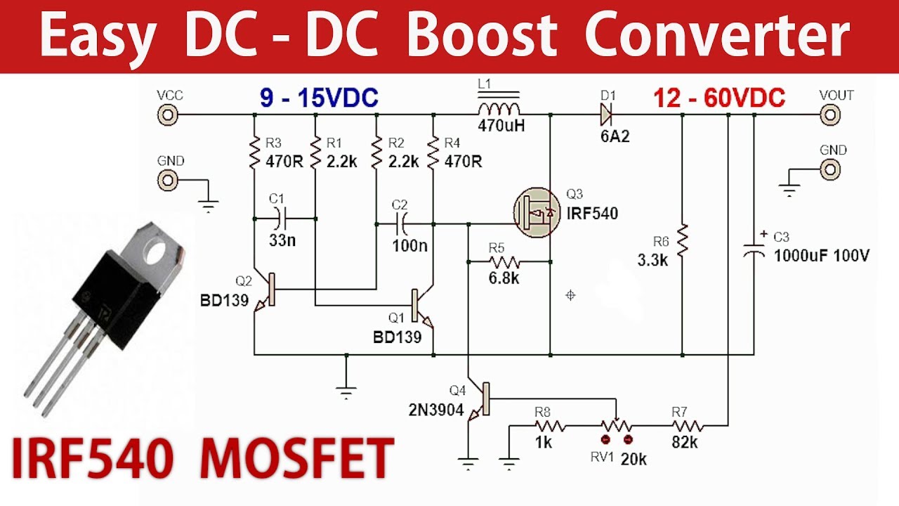
How to make a Simple DC DC Boost Converter Power Supply - YouTube

Simple 3 Amp. Dc To Dc Boost Converter Circuit Diagram

MC34063A Pinout, Example Circuits, Datasheet, Applications,, 40% OFF

DC Boost Converter circuit 3.3-5v to 12V-13.8V - Eleccircuit

Ágyú állhatatos Ernest Shackleton 5v to 12v Philadelphia Fotel hajlamos

Variable Output Voltage DC to DC Boost Converter Circuit Diagram using